친구의 조언을 받아들여 깃허브를 만들었다.
https://github.com/thousrm/universal_NPU-CNN_accelerator/tree/main
버전 관리에 용이해보여 적극적으로 이용할 생각이다.
모듈의 이름을 직관적이지 못하게 지었는데 사실 기능을 생각하면 convolution processor나 그 비슷한게 더 낫다.
또 convolution만 수행하는게 아니라 이후의 후처리 과정에서 몇가지 다른 연산을 수행하기도 하기에 다시 여러개의 세부 모듈로 분할하는게 맞지만... 코드가 별로 길지도 않은데 포트 일일이 또 잡아주기 귀찮아서 그냥 한번에 작성했다... 귀찮은게 문제다 항상
processing element 만이 아니라 다른 모듈들도 always 문을 잘 안쓰고 assign을 주로 사용해서 작성했는데 그 이유는 개인적으로 assign 문이 데이터 흐름을 파악하는데 더 좋기도 하고 혹시 synthesis 할 때 레지스터로 되는 것을 막기위해 가능한 assign 문으로 작성했다.
애초에 synthesis를 할 수 없긴 하지만 이번 프로젝트는 연습을 위한 것인만큼 가능한 세세한 부분까지 하는게 기억을 떠올리고 실력을 향상하는데 더 도움이 될거 같아서 그렇게 했다.
module PE(in, weight, bias, bound_level, step, en, out, out_en, clk, reset);

parameter cell_bit = 8;
parameter N_cell = 9;
parameter biasport = 16;
parameter outport = 8;

parameter outport_mul = 16;
parameter outport_add = 17;

input [cell_bit*N_cell-1:0] in;
input [cell_bit*N_cell-1:0] weight;
input signed [biasport-1:0] bias;
output signed [outport-1:0] out;

input clk, reset;

wire signed [cell_bit-1:0] inp[0:N_cell-1];
wire signed [cell_bit-1:0] wei[0:N_cell-1];

wire signed [outport_mul-1:0] mulout[0:N_cell-1];
wire signed [outport_mul-1:0] d_mulout[0:N_cell-1];
wire signed [outport_add-1:0] addout[0:4];
wire signed [outport_add:0] addout_1[0:3];

genvar i;
generate
for(i=0; i<N_cell; i=i+1) begin : app
   assign inp[i] = in[cell_bit*N_cell-1 - cell_bit*i -: cell_bit];
   assign wei[i] = weight[cell_bit*N_cell-1 - cell_bit*i -: cell_bit];
   M_8 M8(inp[i], wei[i], mulout[i]);
end
endgenerate


input en;
wire en_d;
input [1:0] bound_level;
wire [1:0] bound_level_d;
input [2:0] step;
wire [2:0] step_d;
wire signed [biasport-1:0] bias_d;

D_FF144 FF0 ({mulout[0], mulout[1], mulout[2], mulout[3], mulout[4], mulout[5], mulout[6], mulout[7], mulout[8]},
               {d_mulout[0], d_mulout[1], d_mulout[2], d_mulout[3], d_mulout[4], d_mulout[5], d_mulout[6], d_mulout[7], d_mulout[8]},
                clk, reset);

D_FF1 F3 (en, en_d, clk, reset);
D_FF3 F9 (step, step_d, clk, reset);
D_FF2 F8 (bound_level, bound_level_d, clk, reset);
D_FF16 F_bias(bias, bias_d, clk, reset);


/////////////////////////////////////////////
//clk+1
/////////////////////////////////////////////


A_16 A0 (bias, d_mulout[0], addout[0]);
A_16 A1 (d_mulout[1], d_mulout[2], addout[1]);
A_16 A2 (d_mulout[3], d_mulout[4], addout[2]);
A_16 A3 (d_mulout[5], d_mulout[6], addout[3]);
A_16 A4 (d_mulout[7], d_mulout[8], addout[4]);

A_17 A5 (addout[0], addout[1], addout_1[0]);
A_17 A6 (addout[2], addout[3], addout_1[1]);

A_18_f A7 (addout_1[0], addout_1[1], addout_1[2]);

A_18_f A8 ({addout[4][outport_add-1], addout[4]}, addout_1[2], addout_1[3]);


//assign out = addout_1[3][outport_add-:outport];


////////////////
//adder tree end, output = addout_1[3]
////////////////


////////////////
//set bound
////////////////

wire signed [outport-1:0] b_out;
wire uxnor[1:3], uand[1:2];
assign b_out[7] = addout_1[3][outport_add]; //MSB

assign uxnor[1] = addout_1[3][outport_add] ~^ addout_1[3][outport_add-1];
assign uxnor[2] = addout_1[3][outport_add-1] ~^ addout_1[3][outport_add-2];
assign uxnor[3] = addout_1[3][outport_add-2] ~^ addout_1[3][outport_add-3];

assign uand[1] = uxnor[1] & uxnor[2];
assign uand[2] = uand[1] & uxnor[3];

assign b_out[6:0] = bound_level_d == 2'b01 ?
                   uxnor[1] == 1'b0 ? {~addout_1[3][outport_add], ~addout_1[3][outport_add], ~addout_1[3][outport_add],
                               ~addout_1[3][outport_add], ~addout_1[3][outport_add], ~addout_1[3][outport_add], ~addout_1[3][outport_add]}
                               : addout_1[3][outport_add-2-:7]
               : bound_level_d == 2'b10 ?
                   uand[1] == 1'b0 ? {~addout_1[3][outport_add], ~addout_1[3][outport_add], ~addout_1[3][outport_add],
                               ~addout_1[3][outport_add], ~addout_1[3][outport_add], ~addout_1[3][outport_add], ~addout_1[3][outport_add]}
                               : addout_1[3][outport_add-3-:7]
               : bound_level_d == 2'b11 ?
                   uand[2] == 1'b0 ? {~addout_1[3][outport_add], ~addout_1[3][outport_add], ~addout_1[3][outport_add],
                               ~addout_1[3][outport_add], ~addout_1[3][outport_add], ~addout_1[3][outport_add], ~addout_1[3][outport_add]}
                               : addout_1[3][outport_add-4-:7]
               : addout_1[3][outport_add-1-:7];


////////////////
//set bound end, output = b_out
////////////////

////////////////
//multiple clk adder start
////////////////


reg [2:0] p_step;
reg mux_f_s;
//reg out_en_b;
output reg out_en;

/// counter
always @(posedge clk) begin
   if(reset == 0) begin
       p_step <= 3'b000;
       mux_f_s <= 1'b0;
       out_en <= 1'b0;
   end
   else if (en_d == 1) begin
       if (p_step == step_d) begin
           p_step <= 3'b000;
           out_en <= 1'b1;
           mux_f_s <= 1'b0;
       end
       else begin
           p_step <= p_step +1;
           out_en <= 1'b0;
           mux_f_s <= 1'b1;
       end
   end
   else  begin
       mux_f_s <= 0;
       out_en <= 1'b0;
   end
end

//adder

wire signed [outport-1:0] adder_final_B, adder_final_out;

assign adder_final_B = mux_f_s ? out : 8'b0000_0000;

A_8_f A_final(b_out, adder_final_B, adder_final_out);


///clk+2
D_FF8 F1 (adder_final_out, out, clk, reset);

//D_FF1 F2 (out_en_b, out_en, clk, reset);


endmodule
wire 이름을 정말 중구난방으로 지어서 가독성을 심각하게 떨어뜨린 것을 사과하고 싶다... 오랜만에 코딩을 했더니 어떻게 작명했는지가 기억이 안나서 대충 지어 나가다보니 이 꼴이 나버렸다... 나중에 곱셈기-덧셈기까지 설계가 끝나면 정리할 생각이다.
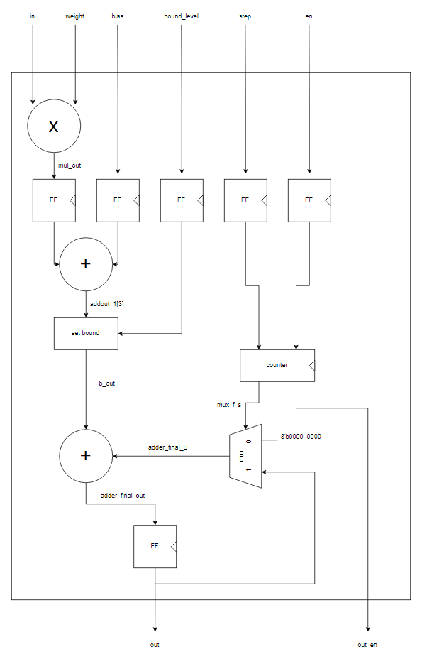
processing_element(이하 pe)는 크게 세가지의 독립된 부분으로 나뉘어 있다. 원래 상술한대로 각각 세부 모듈로 따로 만들었어야했지만 그러기엔 너무 코드 양이 적어서 그냥 한번에 써버렸다.
가장 위의 포트 할당하는 부분은 기능적으로 무언가를 수행하지는 않으니 간단하게 파라미터만 설명하고 넘어가겠다.
cell_bit = 각 input, weight의 비트 수 (8)
parameter N_cell = input 혹은 weight의 개수 (9)
parameter biasport = 들어오는 bias의 비트 수 (16)
parameter outport = output 포트의 비트 수 (8)
parameter outport_mul = 곱셉기의 output 비트 수 (16)
parameter outport_add = 덧셈기 트리의 최종 덧셈기의 output 비트 수 (17)
곱셈기 + 덧셈기
이미 여러번 언급했지만 효율적인 곱셈기+덧셈기를 설계하는 것은 그것만으로도 상당한 일이기에 우선 간단하게 설계하고 넘어가기로 했다.
genvar i;
generate
for(i=0; i<N_cell; i=i+1) begin : app
assign inp[i] = in[cell_bit*N_cell-1 - cell_bit*i -: cell_bit];
assign wei[i] = weight[cell_bit*N_cell-1 - cell_bit*i -: cell_bit];
M_8 M8(inp[i], wei[i], mulout[i]);
end
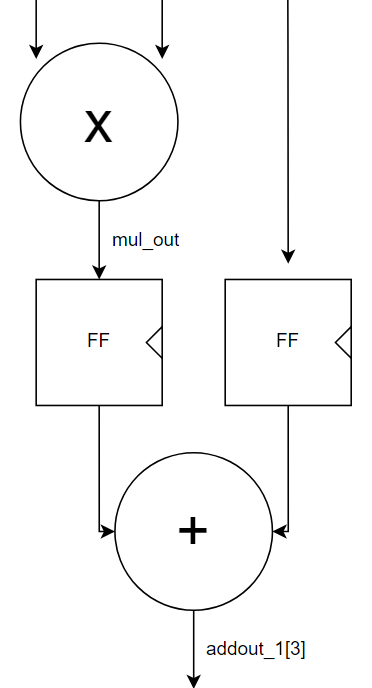
endgenerategenerate 문을 이용해서 귀찮은 포트할당과 곱셈기 배치를 한번에 끝내버리자. 곱셈의 결과들을 mulout들에 저장되어 pipelining을 위한 FF에 할당되어 d_mulout로 다음 clk에 출력된다. (d_mulout이라는 혼자만 튀는 이름은 나중에 mulout_d로 통일할 것이다)
A_16 A0 (bias, d_mulout[0], addout[0]);
A_16 A1 (d_mulout[1], d_mulout[2], addout[1]);
A_16 A2 (d_mulout[3], d_mulout[4], addout[2]);
A_16 A3 (d_mulout[5], d_mulout[6], addout[3]);
A_16 A4 (d_mulout[7], d_mulout[8], addout[4]);
곱셈기의 출력들과 bias는 총 10개로 16비트 덧셈기 5개에 입력되어 17비트 addout들로 출력된다.
A_17 A5 (addout[0], addout[1], addout_1[0]);
A_17 A6 (addout[2], addout[3], addout_1[1]);

A_18_f A7 (addout_1[0], addout_1[1], addout_1[2]);

A_18_f A8 ({addout[4][outport_add-1], addout[4]}, addout_1[2], addout_1[3]);
이후 트리 형식으로 덧셈기를 배치해 계산을 완료한다. 최종 출력은 addout_1[3] 이다.
set bound
해당 부분은 이전에 설명되지 않았던 부분으로 좀 더 상세하게 설명할 예정이다. set bound 기능은 데이터의 크기, 즉 비트 수를 좀 더 효율적으로 사용하기 위해 고안된 기능이다.
예를 들어서 output들 대부분이 -16~15이고 아주 적은 수의 값들만 이 범위를 벗어난다고 하자. 이 경우 그 소수의 값들을 표현하기위해 8비트를 전부 -128부터 127까지 표현하는데 쓴다면 결과적으로 -16~15사이의 값들을 더 상세하게 표현할 수 없고 이는 오히려 신경망의 정확도를 떨어뜨릴 수 있다.
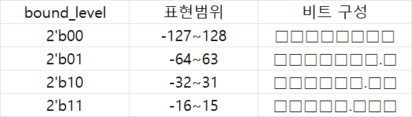
이때 -16 미만 15 초과의 값들을 전부 -16 혹은 15로 출력해 하한값과 상한값을 설정한다면 xxxxx.xxx로 3개 비트를 소수점을 표현하는데 사용해 해당 구간에 밀집된 값들을 더 상세하게 표현할 수 있다.
신경망에 따라 다르겠으나 이런 식으로 값의 범위를 추가적으로 제한시켜 본래 큰 값과 작은 값들을 표현하는데 쓰이던 비트들을 밀집된 구간을 표현하는데 사용한다면 정확도를 향상시킬 수 있지 않을까하고 추가한 기능이 바로 이 set bound 기능이다.
wire signed [outport-1:0] b_out;
wire uxnor[1:3], uand[1:2];
assign b_out[7] = addout_1[3][outport_add]; //MSB

assign uxnor[1] = addout_1[3][outport_add] ~^ addout_1[3][outport_add-1];
assign uxnor[2] = addout_1[3][outport_add-1] ~^ addout_1[3][outport_add-2];
assign uxnor[3] = addout_1[3][outport_add-2] ~^ addout_1[3][outport_add-3];

assign uand[1] = uxnor[1] & uxnor[2];
assign uand[2] = uand[1] & uxnor[3];

assign b_out[6:0] = bound_level_d == 2'b01 ?
                    uxnor[1] == 1'b0 ? {~addout_1[3][outport_add], ~addout_1[3][outport_add], ~addout_1[3][outport_add],
                                ~addout_1[3][outport_add], ~addout_1[3][outport_add], ~addout_1[3][outport_add], ~addout_1[3][outport_add]}
                                : addout_1[3][outport_add-2-:7]
                : bound_level_d == 2'b10 ?
                    uand[1] == 1'b0 ? {~addout_1[3][outport_add], ~addout_1[3][outport_add], ~addout_1[3][outport_add],
                                ~addout_1[3][outport_add], ~addout_1[3][outport_add], ~addout_1[3][outport_add], ~addout_1[3][outport_add]}
                                : addout_1[3][outport_add-3-:7]
                : bound_level_d == 2'b11 ?
                    uand[2] == 1'b0 ? {~addout_1[3][outport_add], ~addout_1[3][outport_add], ~addout_1[3][outport_add],
                                ~addout_1[3][outport_add], ~addout_1[3][outport_add], ~addout_1[3][outport_add], ~addout_1[3][outport_add]}
                                : addout_1[3][outport_add-4-:7]
                : addout_1[3][outport_add-1-:7];
bound_level이 0인 경우 추가적인 제한없이 -128~127이 그대로 출력, 1인 경우 -64~63으로 제한해 1개 비트를 소수점으로 사용, 2인 경우 -32~31로 제한해 2개 비트를 소수점으로 사용, 3인 경우 -16~15로 제한해 3개 비트를 소수점으로 사용한다.
정리하면 이와 같다.
값의 범위가 추가적으로 제한되었으므로 그 제한을 벗어나는 값들이 제한범위내로 수정되어야한다. 즉 오버플로우, 언더플로우 여부를 체크해야한다.
제한범위를 벗어나는지 여부는 xnor과 and를 이용해 체크할 수 있는데 이는 예를 들어 8비트 범위 내의 각 값들을 표시했을 때 다음과 같이 비트가 배열되기 때문이다.
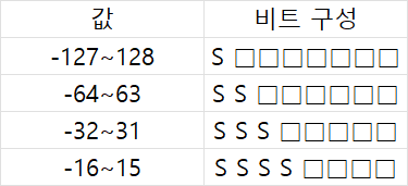
S는 sign bit를 뜻한다. -64~63의 값을 갖는 경우 2번째 bit가 sign bit인 MSB와 항상 같고, -32~31의 경우 상위 3개 bit가, -16~15의 경우 상위 4개 bit가 항상 같은 값을 갖는다.
xnor의 경우 두 값이 같을 경우 1, 다를 경우 0을 출력하는데 이를 이용한다면 제한 범위를 벗어나는 값들을 판별할 수 있다.
예를 들어서 bound_level = 2'b10을 입력해 값의 범위가 -32~31로 제한되었는데 상위 3개 bit의 값이 전부 같지 않다면 이는 제한 범위를 벗어난 값이라는 뜻이다.
assign uxnor[1] = addout_1[3][outport_add] ~^ addout_1[3][outport_add-1];
assign uxnor[2] = addout_1[3][outport_add-1] ~^ addout_1[3][outport_add-2];
assign uxnor[3] = addout_1[3][outport_add-2] ~^ addout_1[3][outport_add-3];
이렇게 xnor에 인접한 비트들끼리 입력되게 한 후 이들을
assign uand[1] = uxnor[1] & uxnor[2];
assign uand[2] = uand[1] & uxnor[3];
and에 입력시키면 해당 값이 어느 범위를 벗어나는지를 알 수 있다.
만약 uxnor[1]=1이 아니라면 상위 2개 bit의 값이 같지 않다는 뜻이고
만약 uand[1]=1이 아니라면 상위 3개 bit의 값이 전부 같지 않다는 뜻이며
만약 uand[2]=1이 아니라면 상위 4개 bit의 값이 전부 같지 않다는 뜻이다.
이들을 이용해 bound_level에 따라 하위 7개 bit에 알맞은 값이 할당되도록 한다.
assign b_out[6:0] = bound_level_d == 2'b01 ?
                    uxnor[1] == 1'b0 ? {~addout_1[3][outport_add], ~addout_1[3][outport_add], ~addout_1[3][outport_add],
                                ~addout_1[3][outport_add], ~addout_1[3][outport_add], ~addout_1[3][outport_add], ~addout_1[3][outport_add]}
                                : addout_1[3][outport_add-2-:7]
                : bound_level_d == 2'b10 ?
                    uand[1] == 1'b0 ? {~addout_1[3][outport_add], ~addout_1[3][outport_add], ~addout_1[3][outport_add],
                                ~addout_1[3][outport_add], ~addout_1[3][outport_add], ~addout_1[3][outport_add], ~addout_1[3][outport_add]}
                                : addout_1[3][outport_add-3-:7]
                : bound_level_d == 2'b11 ?
                    uand[2] == 1'b0 ? {~addout_1[3][outport_add], ~addout_1[3][outport_add], ~addout_1[3][outport_add],
                                ~addout_1[3][outport_add], ~addout_1[3][outport_add], ~addout_1[3][outport_add], ~addout_1[3][outport_add]}
                                : addout_1[3][outport_add-4-:7]
                : addout_1[3][outport_add-1-:7];
8개 bit로 표현되는 값의 최대, 최소는 0111_1111, 1000_0000이므로 범위를 벗어나는 경우 해당 값들이 할당되게 하고 그렇지 않은 경우는 그대로 출력되게 한다.
어째서 하위 7개 bit만 여기서 할당하냐면 최상위 bit는 signed bit로 변함이 없으므로 상단의
assign b_out[7] = addout_1[3][outport_add]; //MSB여기에서 이미 할당이 끝나있다.
이후의 counter 부분은 별로 길지는 않지만 timing을 결정하는 중요한 부분이라 다음 포스팅에서 따로 다루겠다.

정말 좋은 정보 감사합니다!