(Jetson Project#5)Integrating the MPU9250 B184 9-Axis IMU Sensor
Developing Self Driving with Jetson Nano
3.1. Hardware Connection
The MPU9250 can communicate via either I2C or SPI. For simplicity and broad compatibility, we'll use I2C.
3.1.1. Wiring the MPU9250 to Jetson Nano
Components Needed:
- MPU9250 B184 IMU Sensor
- Jumper Wires
- Breadboard (optional, for easier connections)
Connection Diagram:
MPU9250 Pin	                      Jetson Nano Pin
VCC	                    3.3V (Pin 1)
GND	                    Ground (Pin 6)
SCL	                    I2C SCL (Pin 5, GPIO3)
SDA	                    I2C SDA (Pin 3, GPIO2)
AD0	                    Ground (for I2C address 0x68)
CS	                    Not connected (since we're using I2C)
Notes:
-
Voltage Level:
Ensure that the MPU9250 is powered with 3.3V to prevent damage. -
I2C Address:
With AD0 connected to GND, the I2C address is 0x68.
If connected to 3.3V, it becomes 0x69. -
Pull-Up Resistors:
The Jetson Nano's I2C pins already have pull-up resistors.
If you encounter communication issues, you may need to add external pull-up resistors (4.7kΩ) between SCL/SDA and 3.3V.
3.1.2. Enable I2C on Jetson Nano
By default, I2C might be disabled on the Jetson Nano. Follow these steps to enable it:
Install I2C Tools:
sudo apt update
sudo apt install -y i2c-tools
Check if I2C is Enabled:
Run the following command to list I2C buses:
ls /dev/i2c-*Expected Output:
/dev/i2c-13.2. Software Setup
3.2.1. Verify I2C Connection
Before integrating with ROS, ensure that the Jetson Nano can communicate with the MPU9250.
Detect the MPU9250 on the I2C Bus:
sudo i2cdetect -y 1Expected Output:
     0  1  2  3  4  5  6  7  8  9  a  b  c  d  e  f
00:          -- -- -- -- -- -- -- --
10: -- -- -- -- -- -- -- -- -- -- -- -- -- -- -- --
20: -- -- -- -- -- -- -- -- -- -- -- -- -- -- -- --
30: -- -- -- -- -- -- -- -- -- -- -- -- -- -- -- --
40: -- -- -- -- -- -- -- -- -- -- -- -- -- -- -- --
50: -- -- -- -- -- -- -- -- 68 -- -- -- -- -- -- --
60: -- -- -- -- -- -- -- -- -- -- -- -- -- -- -- --
70: -- -- -- -- -- -- -- --
- 68 indicates the MPU9250 is detected at address 0x68.
- If you see 69, the address is 0x69.
- If no device is detected, recheck your wiring and ensure the device is powered.
3.2.2. Install ROS Package for MPU9250
We'll use the mpu9250 ROS package, which provides drivers to publish IMU data.
Clone the MPU9250 ROS Package:
cd ~/catkin_ws/src
git clone https://github.com/ros-drivers/mpu9250.git
Install Dependencies:
cd ~/catkin_ws
rosdep install --from-paths src --ignore-src -r -y
Build the Package:
catkin_make
source devel/setup.bash
3.2.3. Configure the MPU9250 Node
Locate the Launch File:
The package may provide example launch files. Navigate to the package's launch directory:
cd ~/catkin_ws/src/mpu9250/launchEdit the Launch File:
If an example launch file isn't present, create one. For illustration, let's assume we're creating mpu9250.launch.
mkdir -p ~/catkin_ws/src/mpu9250/launch
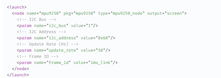
nano ~/catkin_ws/src/mpu9250/launch/mpu9250.launchAdd the Following Content:
<launch>
  <node name="mpu9250" pkg="mpu9250" type="mpu9250_node" output="screen">
    <!-- I2C Bus -->
    <param name="i2c_bus" value="1"/>
    <!-- I2C Address -->
    <param name="i2c_address" value="0x68"/>
    <!-- Update Rate (Hz) -->
    <param name="update_rate" value="50"/>
    <!-- Frame ID -->
    <param name="frame_id" value="imu_link"/>
  </node>
</launch>
Explanation of Parameters:
i2c_bus: The I2C bus number (1 for /dev/i2c-1).
i2c_address: I2C address of the MPU9250 (0x68).
update_rate: Frequency at which IMU data is published (50 Hz is standard).
frame_id: TF frame associated with the IMU data (imu_link).
Create the Frame in TF
Ensure that the TF frames are correctly set up for proper data integration. If you don't have a robot description (URDF/Xacro), you can manually broadcast the TF frames.
For simplicity, we'll proceed without a URDF, but integrating with one is recommended for more complex robots.
3.2.4. Launch the MPU9250 Node
Open a New Terminal (Terminal 4):
Source the ROS Environment:
source /opt/ros/noetic/setup.bash
source ~/catkin_ws/devel/setup.bash
Launch the MPU9250 Node:
roslaunch mpu9250 mpu9250.launch
Verify IMU Data Publication:
List Active Topics:
rostopic list
Expected Output:
/imu/data
/rosout
/rosout_agg
/tf
/tf_static
Echo IMU Data:
rostopic echo /imu/data
Expected Output:
header:
  seq: 123
  stamp:
    secs: 1625097600
    nsecs: 123456789
  frame_id: "imu_link"
orientation:
  x: 0.0
  y: 0.0
  z: 0.0
  w: 1.0
orientation_covariance: [0.0, 0.0, 0.0, 0.0, 0.0, 0.0, 0.0, 0.0, 0.0]
angular_velocity:
  x: 0.0
  y: 0.0
  z: 0.0
angular_velocity_covariance: [0.0, 0.0, 0.0, 0.0, 0.0, 0.0, 0.0, 0.0, 0.0]
linear_acceleration:
  x: 0.0
  y: 0.0
  z: 9.8
linear_acceleration_covariance: [0.0, 0.0, 0.0, 0.0, 0.0, 0.0, 0.0, 0.0, 0.0]
3.2.5. Calibrate the MPU9250 (Optional but Recommended)
Calibration ensures accurate orientation and movement data.
Collect Calibration Data:
Place the MPU9250 on a stable, flat surface and ensure it's stationary.
Use ROS Tools or External Scripts:
Option 1: Use imu_calibration packages available in ROS.
Option 2: Implement your own calibration routine by averaging readings to determine biases.
Apply Calibration Parameters:
Update the launch file or node parameters to include calibration offsets for orientation and acceleration.
Example:
<param name="orientation_offset" value="[0.0, 0.0, 0.0, 1.0]"/>
<param name="acceleration_offset" value="[0.0, 0.0, 0.0]"/>
Note: Replace the values with your calibrated offsets.