
ACL
그동안 ACL에 대해 세번의 포스트를 했었다.
ACL - 1, ACL - 2, ACL - 3 이렇게 세 번인데, Extended ACL에 대해서는 이번에 다뤄보려고 한다.
이번 포스트에서도 CCNA과정을 바탕으로한 실습 내용으로 작성해보았다.
Extended ACL
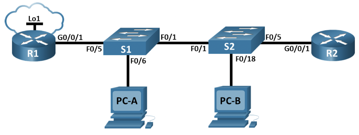
- 토폴로지 및 IP 주소 테이블
- 네트워크 구성 및 장비별 기본 설정
- 스위치 VLAN 구성
- 라우팅 구성
- 원격 접속 구성
- Extended ACL 구성
토폴로지 및 IP 주소 테이블
-
토폴로지
-
IP 주소 테이블
| 장비 | 인터페이스 | IP 주소 | 서브넷 마스크 | 게이트웨이 |
|---|---|---|---|---|
| R1 | g0/1 | |||
| g0/1.10 | 10.20.0.1 | 255.255.255.0 | ||
| g0/1.20 | 10.30.0.1 | 255.255.255.0 | ||
| g0/1.30 | 10.40.0.1 | 255.255.255.0 | ||
| g0/1.1000 | ||||
| Loopback | 172.16.1.1 | 255.255.255.0 | ||
| R2 | g0/1 | 10.20.0.4 | 255.255.255.0 | |
| S1 | VLAN 20 | 10.20.0.2 | 255.255.255.0 | 10.20.0.1 |
| S2 | VLAN 20 | 10.20.0.3 | 255.255.255.0 | 10.20.0.1 |
| PC-A | NIC | 10.30.0.10 | 255.255.255.0 | 10.30.0.1 |
| PC-B | NIC | 10.40.0.10 | 255.255.255.0 | 10.40.0.1 |
- VLAN 테이블
| VLAN | 이름 | 할당 인터페이스 |
|---|---|---|
| 20 | Management | S2: Fa0/5 |
| 30 | Operations | S1: Fa0/6 |
| 40 | Sales | S2: Fa0/18 |
| 999 | ParkingLot | S1: F0/2-4, F0/7-24, G0/1-2 |
| S2: F0/2-4, F0/6-17, F0/19-24, G0/1-2 | ||
| 1000 | Native |
네트워크 구성 및 기본 설정
- 네트워크 구성
실제 실습 했을 때 R2: g0/1과 S2: Fa0/18이 랙에 없어서 다른 포트인 R2: g0/1 -> R2: g0/0, S2: Fa0/18 -> S2: Fa0/10로 구성했다. - 기본 설정(Router)
Router> en
Router# conf t
Router(config)# ho R1
R1(config)# no ip domain-lookup
R1(config)# enable secret class
R1(config)# line con 0
R1(config-line)# password cisco
R1(config-line)# login
R1(config-line)# line vty 0 4
R1(config-line)# password cisco
R1(config-line)# login
R1(config-line)# exit
R1(config)# service password-encrytion
R1(config)# banner motd @ DO NOT ENTER WITHOUT PERMISSION @
R1(config)# end
R1# copy running-config startup-config- 기본 설정(Switch)
Switch> en
Switch# conf t
Switch(config)# ho S1
S1(config)# no ip domain-lookup
S1(config)# enable secret class
S1(config)# line con 0
S1(config-line)# password cisco
S1(config-line)# login
S1(config-line)# line vty 0 15
S1(config-line)# login
S1(config-line)# exit
S1(config)# service password-encryption
S1(config)# banner motd @ DO NOT ENTER WITHOUT PERMISSION @
S1(config)# end
S1# copy running-config startup-config
- 라우터와 스위치의 명령어들을 보면 알 수 있듯이 초기 설정은 두 장비 모두 동일하다.
- 토폴로지에 나와있는 것처럼 물리적으로 연결 후 Serial로 연결된 컴퓨터에서 putty 등으로 접속하여 해당 명령어들로 설정을 해준다.
- 라우터와 스위치가 두 개씩 있으나 초기 설정은 hostname만 다르게 하고 동일하다.
- 물론 경우에 따라 login시 비밀번호와 banner motd는 다르게 설정해도 된다.
스위치 VLAN 구성
- 스위치에서 VLAN 설정(S1)
S1# conf t
S1(config)# vlan 20
S1(config-vlan)# name Management
S1(config-vlan)# vlan 30
S1(config-vlan)# name Operations
S1(config-vlan)# vlan 40
S1(config-vlan)# name Sales
S1(config-vlan)# vlan 999
S1(config-vlan)# name ParkingLot
S1(config-vlan)# vlan 1000
S1(config-vlan)# name Native
S1(config-vlan)# exit
S1(config)# int vlan 20
S1(config-if)# ip addr 10.20.0.2 255.255.255.0
S1(config-if)# no shut
S1(config-if)# exit
S1(config)# ip default-gateway 10.20.0.1
S1(config)# int range fa0/2 - 4, fa0/7 - 24, g0/1 - 2
S1(config-if-range)# switchport mode access
S1(config-if-range)# switchport access vlan 999
S1(config-if-range)# shut
S1(config-if-range)# exit
S1(config)# int fa0/6
S1(config-if)# swithchport mode access
S1(config-if)# switchport access vlan 30
S1(config-if)# end
- VLAN을 알맞게 설정하고 각 IP 주소 테이블을 참고하여 게이트웨이와 IP 주소를 알맞게 구성한다.
- 토폴로지에 나와있는 포트가 아닌 사용하지 않는 포트는 ParkingLot VLAN에 할당하여 비활성화 하는 작업을 수행한다.
- 나머지 사용된 포트는 위의 VLAN 테이블에서 볼 수 있는 것처럼 할당한다.
- 스위치에서 VLAN설정(S2)
S2# conf t
S2(config)# vlan 20
S2(config-vlan)# name Management
S2(config-vlan)# vlan 30
S2(config-vlan)# name Operations
S2(config-vlan)# vlan 40
S2(config-vlan)# Sales
S2(config-vlan)# vlan 999
S2(config-vlan)# ParkingLot
S2(config-vlan)# vlan 1000
S2(config-vlan)# Native
S2(config-vlan)# exit
S2(config)# int vlan 20
S2(config-if)# ip addr 10.20.0.3 255.255.255.0
S2(config-if)# no shut
S2(config-if)# exit
S2(config)# ip default-gateway 10.20.0.1
S2(config)# int range fa0/2 - 4, fa0/6 - 9, fa0/11 - 24, g0/1 - 2
S2(config-if-range)# switchport mode access
S2(config-if-range)# switchport access vlan 999
S2(config-if-range)# shut
S2(config-if-range)# exit
S2(config)# int fa0/5
S2(config-if)# switchport mode access
S2(config-if)# switchport access vlan 20
S2(config-if)# int fa0/10
S2(config-if)# switchport mode access
S2(config-if)# switchport access vlan 40
S2(config-if)# end
- S1에서 설정한 것과 다른 점은 vlan테이블에 나와있는 것처럼 포트를 할당한 것이고 특히 네트워크 구성단계에서 설명한 것처럼 fa0/18을 fa0/10으로 바꿔 구성했기 때문에 fa0/10을 vlan 40에 구성했다는 것이다.
- VLAN 구성 확인(S1)
S1# sh vlan br
VLAN 	Name				Status		Ports
————	————				——————		—————
1		default				active		Fa0/1, Fa0/5
20		Management			active
30		Operations			active		Fa0/6
40		Sales				active
999		ParkingLot			active		Fa0/2, Fa0/3, Fa0/4, Fa0/7
										Fa0/8, Fa0/9, Fa0/10, Fa0/11
										Fa0/12, Fa0/13, Fa0/14, Fa0/15
										Fa0/16, Fa0/17, Fa0/18, Fa0/19
										Fa0/20, Fa0/21, Fa0/22, Fa0/23
										Fa0/24, Gig0/1, Gig0/2
1000 	Native				active
1002 	fddi-default		active
1003 	token-ring-default	active
1004 	fddinet-default		active
1005 trnet-default active- VLAN 구성 확인(S2)
S1# sh vlan br
VLAN 	Name				Status		Ports
————	————				——————		—————
1		default				active		Fa0/1
20		Management			active
30		Operations			active
40		Sales				active		Fa0/10
999		ParkingLot			active		Fa0/2, Fa0/3, Fa0/4, Fa0/5
										Fa0/6, Fa0/7, Fa0/8, Fa0/9
										Fa0/11, Fa0/12, Fa0/13, Fa0/14
										Fa0/15, Fa0/16, Fa0/17, Fa0/18
										Fa0/19, Fa0/20, Fa0/21, Fa0/22
										Fa0/23, Fa0/24, Gig0/1, Gig0/2
1000 	Native				active
1002 	fddi-default		active
1003 	token-ring-default	active
1004 	fddinet-default		active
1005 	trnet-default		active
- 두 개의 스위치 모두 설정한 것처럼 각 VLAN에 구성된 것을 확인할 수 있다.
- 트렁킹 구성
S1# conf t
S1(config)# int fa0/1
S1(config-if)# switchport mode trunk
S1(config-if)# switchport trunk native vlan 1000
S1(config-if)# switchport trunk allowed vlan 20, 30, 40, 1000
S1(config-if)# end
S1# sh int trunk
Port	Mode	Encapsulation	Status		Native vlan
Fa0/1	on		802.1q			trunking	1000

Port	Vlans allowed on trunk
Fa0/1	20,30,40,1000

Port	Vlans allowed and active in management domain
Fa0/1	20,30,40,1000

Port	Vlans in spanning tree forwarding state and not pruned
Fa0/1	20,30,40,1000
- S1과 S2의 vlan을 트렁크 인터페이스로 구성하는 과정은 동일하다.
- S1의 fa0/5포트도 fa0/1과 같이 수동으로 트렁크 인터페이스를 설정한다.
라우터로 가는 트렁크
S1# conf t
S1(config)# int fa0/5
S1(config-if)# switchport mode trunk
S1(config-if)# switchport trunk native vlan 1000
S1(config-if)# switchport trunk allowed vlan 20, 30, 40, 1000
S1(config-if)# end
S1# copy runnning-config startup-config
라우팅 구성
R1# conf t
R1(config)# int g0/1
R1(config-if)# no shut
R1(config-if)# int g0/1.20
R1(config-subif)# description Management Network
R1(config-subif)# encapsulation dot1Q 20
R1(config-subif)# ip addr 10.20.0.1 255.255.255.0
R1(config-subif)# int g0/1.30
R1(config-subif)# description Operations Network
R1(config-subif)# encapsulation dot1Q 30
R1(config-subif)# ip addr 10.30.0.1 255.255.255.0
R1(config-subif)# int g0/1.40
R1(config-subif)# description Sales Network
R1(config-subif)# encapsulation dot1Q 40
R1(config-subif)# ip addr 10.40.0.1 255.255.255.0
R1(config-subif)# int g0/1.1000
R1(config-subif)# description Native VLAN
R1(config-subif)# encapsulation dot1Q 1000 native
R1(config-subif)# exit
R1(config)# int loopback 1
R1(config-if)# ip addr 172.168.1.1 255.255.255.0
R1(config-if)# end
- 맨 위의 IP 주소테이블과 VLAN 테이블을 참고하여 각 인터페이스에 맞게 IP를 설정하고 loopback 1 까지 구성한 모습이다.
R1# sh ip int br
Interface					IP-Address	OK? Method 	Status					Protocol
Emabedded-Service-Engine/0	unassigned	YES	unset	administratively down	down
GigabitEthernet0/0			unassigned	YES unset 	administratively down	down
GigabitEthernet0/1			unassigned	YES unset	up						up
GigabitEthernet0/1.20		10.20.0.1	YES manual 	up						up
GigabitEthernet0/1.30		10.30.0.1	YES manual 	up						up
GigabitEthernet0/1.40		10.40.0.1	YES manual 	up						up
GigabitEthernet0/1.1000		unassigned	YES unset	administratively down	down
Serial0/0/0					unassigned	YES unset	administratively down 	down
Serial0/0/1					unassigned	YES unset	administratively down 	down
Loopback1					172.16.1.1	YES manual	up						up
- 위 명령어를 통해 인터페이스 구성이 잘 되었는지 확인할 수 있다.
R2# conf t
R2(config)# int g0/0
R2(config-if)# ip addr 10.20.0.4 255.255.255.0
R2(config-if)# no shut
R2(config-if)# exit
R2(config)# ip route 0.0.0.0 0.0.0.0 10.20.0.1
- R2에서는 next hop 10.20.0.1로 기본 경로를 사용해 g0/0을 구성했다.
원격 접속 구성
R1# conf t
R1(config)# username SSHadmin secret $cisco123!
R1(config)# ip domain name ccna-lab.com
R1(config)# crypto key generate rsa general-keys modulus 1024
R1(config)# line vty 0 4
R1(config-line)# transport input ssh
R1(config-line)# login local
R1(config-line)# exit
R1(config)# ip http secure-server
R1(config)# ip http authentication local
R1(config)# end
- SSH 지원을 위해 사용자 이름과 암호를 설정 후 1024비트 계수를 사용하여 암호화 키를 사용한다.
- 로컬 사용자 데이터베이스를 이용하도록 vty를 구성한다.
- 도메인 이름은 ccna-lab.com으로 설정한다.
- 그 후 R1에서 HTTP를 활성화하고 사용자 인증을 할 수 있도록 구성한다.
Extended ACL 구성
R1# conf t
R1(config)# access-list 101 remark ACL 101 fulfills policies 1, 2, and 3
R1(config)# access-list 101 deny tcp 10.40.0.0 0.0.0.255 10.20.0.0 0.0.0.255 eq 22
R1(config)# access-list 101 deny tcp 10.40.0.0 0.0.0.255 10.20.0.0 0.0.0.255 eq 80
R1(config)# access-list 101 deny tcp 10.40.0.0 0.0.0.255 10.30.0.0 0.0.0.0 eq 80
R1(config)# access-list 101 deny tcp 10.40.0.0 0.0.0.255 10.40.0.0 0.0.0.0 eq 80
R1(config)# access-list 101 deny tcp 10.40.0.0 0.0.0.255 10.30.0.0 0.0.0.0 eq 80
R1(config)# access-list 101 deny tcp 10.40.0.0 0.0.0.255 10.20.0.0 0.0.0.255 eq 443
R1(config)# access-list 101 deny tcp 10.40.0.0 0.0.0.255 10.20.0.0 0.0.0.0 eq 443
R1(config)# access-list 101 deny tcp 10.40.0.0 0.0.0.255 10.40.0.0 0.0.0.0 eq 443
R1(config)# access-list 101 deny icmp 10.40.0.0 0.0.0.255 10.20.0.0 0.0.0.255 echo
R1(config)# access-list 101 deny icmp 10.40.0.0 0.0.0.255 10.30.0.0 0.0.0.255 echo
R1(config)# access-list 101 permit ip any any
R1(config)# int g0/1.40
R1(config-subif)# ip access-group 101 in
R1(config-subif)# exit
R1(config)# access-list 102 remark ACL 102 fulfills policies 4
R1(config)# access-list 102 deny icmp 10.30.0.0 0.0.0.255 10.40.0.0 0.0.0.255 echo
R1(config)# access-list 102 permit ip any any
R1(config)# int g0/1.30
R1(config-subif)# ip access-group 102 in
- ACL 101과 ACL 102 두가지의 ACL을 생성하고 적용하고자 하는 프로토콜에 대해 ACL정책을 적용한 과정이다.

아침엔 운동하고 밤엔 잠을 잔다.