JK flip flop Moore model circuit
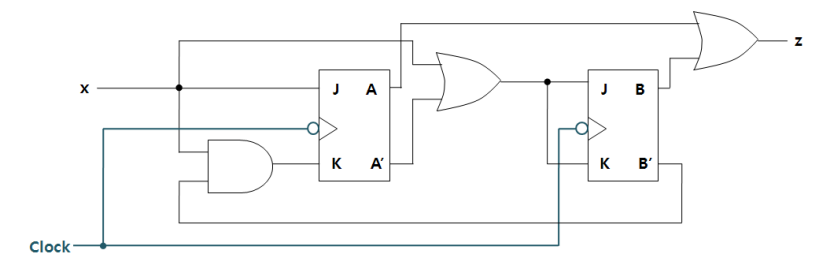
JK 플립플롭을 사용한 Moore model circiuit을 살피어 보자 위의 회로를 통해 Boolean Equation을 구성해 보면
JA=X
KA=xB'
JB=Kb=X+A'
z=A+B
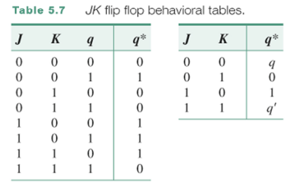
JK 플립플롭의 behavior table을 살피어 보자. 왼쪽 단순화된 식을 보면 이전에 나온 JK와 동일한 것을 확인할 수 있다.
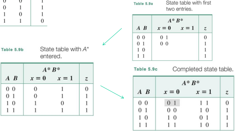
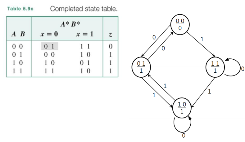
Boolean equation에 맞추어서 state table을 제작해 보면 위와 같이 구성되는 것을 확인할 수 있다.
위의 식을 그래서 state diagram으로 표현하면 다음과 같이 된다.
A Mealy Model
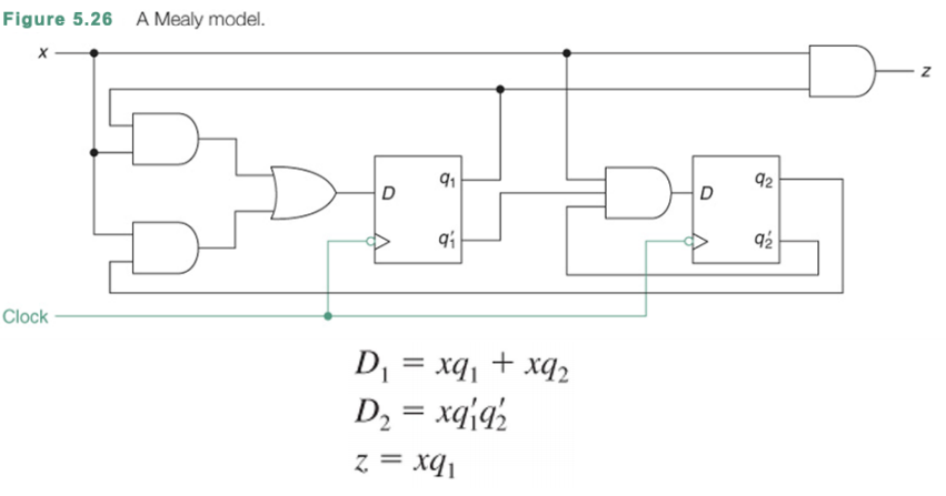
이번에는 입력이 결과에 영향을 미치는 밀리 머신을 봐보자. 여기에서는 state와 출력 z 모두에 input이 dependent하기 때문에 Mealy Machine이라고 부른다.
그래서 위의 함수식으로 state table을 만들어 보자
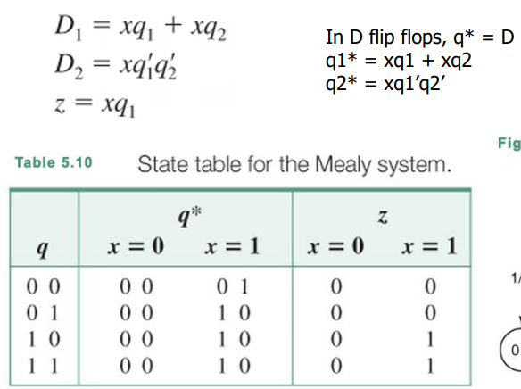
위의 state table을 보았을 때 Moore Machine과의 차이점은 z가 x에 의해 값이 변화한다는 것을 확인할 수 있다는 점이다.
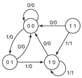
이러한 state table을 활용하여 state diagram을 구성하면 위와 같이 형성된다.
ch6. The Design of Sequential Systems
Design procedure
- 회로 동작 기술 : Specification
- 정의된 회로의 상태표 작성 : Formulation - Obtain a state diagram or state table
- 필요한 경우 상태 축소 및 상태 할당 : State Assignment - Assign binary codes to the states
- 플립플롭의 수와 종류 결정 : Flip-Flop Input Equation Determination - Select flip-flop types and derive flip-flop equations from next state entries in the table
- 플립플롭의 입력, 출력 및 각각의 상태에 문자기호 부여: Output Equation Determination - Derive output equations from output entries in the table
- 상태표를 이용한 회로의 상태 여기표 작성 : Optimization - Optimize the equations
- 간소화 방법을 이용하여 출력함수 및 플립플롭의 입려감수 유도 : Technology Mapping - Find circuit from equations and map to flip-flops and gate technology
- 순서논리회로도 작성 : Verification - Verify correctness of final design
Specification
- Informal description
- Written description
- Mathmatical description
- Hardware description language(HDL - verilog)
- Tabular description
- Equation description
- Diagram describing operation (not just structure)
Formulation: Finding a state diagram
state : 입력 변화에 기반해서 만들어진 an abstraction of history of the past
example)
과거에 입력 1이 있었다면 A state에 가 있을 것이다.
1 다음에 0이 들어 왔다면 B state에 가 있을 것이다.
이런식으로 state에 따라 과거에 어떤 상태인지 알 수가 있다.
그래서 우리가 회로를 기술할때 state를 사용하게 되는데 past input sequence을 기억하여 state에 적용하고 결론적으로 우리가 원하는 output을 만들어 내기 위해 state를 사용한다.
sequence recognizer : 우리가 정해 놓은 패턴을 찾는 sequence circuit으로 찾았을 때 1또는 0을 반환한다.
그래서 이 아래로는 sequence recognizer을 설계하는과정을 통해 sequence circuit을 만드는 과정을 이해할 예정이다.
Sequence Recognizer Procedure
- Reset을 계속 눌러서 initial state가 되도록 만들기 : Begin in an initial state in which NONE of the initial portion of the sequence has occurred (typically “reset” state).
– Add a state that recognizes that the first symbol has occurred.
– Add states that recognize each successive symbol occurring.
– The final state represents the input sequence occurrence.
– 중간에 잘 못 된 패턴이 들어왔을 때 initial state로 돌아가는 transition arcs도 표시 : Add state transition arcs which specify what happens when a symbol not in the proper sequence has occurred.
– 중간 state부터 시작하는 arc들을 표시하라 : Add state transition arcs which specify substrings.
State Assignment
state(m)은 반드시 유니크 해야한다.
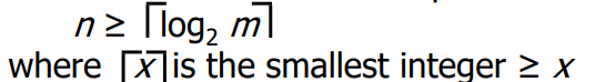
4개의 state(m)가 존재한다면 못해도 logm 반올림 한 값 이상의 n bit가 필요하다.
최소 bit 이상을 사용하면 조금 더 유용하다.
2^n - m 개의 사용하지 않는 상태가 남게된다.
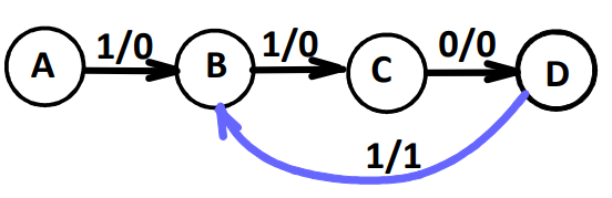
Sequence Recognizer Example
예를 들어 1101 패턴을 인지해야 한다고 생각해보자
우선 1111101 과 같은 경우 1101을 인식해야 하고
1101101 인 경우 Overlap된 것을 정확하게 인식할 수 있어야 한다.
그래서 위의 경우에 대해서 state machine을 디자인 해보자
- state를 정의해 보자
first symbol에서 시작해서 그다음 상태로 계속해서 이동하고 만약 우리가 패턴을 찾아냈다면 1을 반환하고 그 외에는 0을 반환한다.
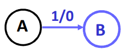
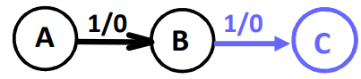
그래서 A state에서 1을 발견해서 B state로 이동하는데 이때 출력 0의 의미는 아직 우리가 원하는 패턴을 찾아내지 못했다는 의미이다.
그 다음 1이 다시 들어왔을 때 C state로 이동한다.
그리고 또 0 이 들어오고 1이 순서대로 들어온다면 Output 1이 된다.
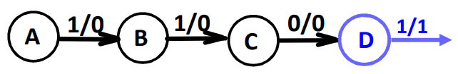
이런식으로 Mealy Machine을 구성할 수 있는데 만약에 overlapping이 발생한다면 어떻게 할까? 이를 위해서 State를 다음과 같이 구성하자