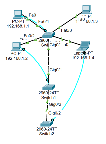
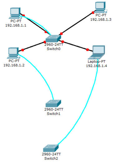
Network diagram
This lab will test your ability to configure speed, duplex, and vlan settings on the network interfaces of a Catalyst 2960 switch.
Questions
Q1. Configure each Switch0 fastethernet switchport for operation.
Upon taking a brief look at the running-config, you can notice that the configuration for each interface connected to the PCs has been misconfigured.
!
interface FastEthernet0/1
 duplex half
 speed 10
 shutdown
!
interface FastEthernet0/2
 duplex half
 speed 100
!
interface FastEthernet0/3
 duplex half
 speed 10
!
interface FastEthernet0/4
 switchport access vlan 10
 duplex half
 shutdown
Configure the duplex mode, set its speed, and enable these interfaces:
Switch(config)#int range fastEthernet 0/1 - 4
Switch(config-if-range)#duplex full
Switch(config-if-range)#
%LINK-5-CHANGED: Interface FastEthernet0/2, changed state to up

%LINEPROTO-5-UPDOWN: Line protocol on Interface FastEthernet0/2, changed state to up
speed 100
Switch(config-if-range)#
%LINK-5-CHANGED: Interface FastEthernet0/3, changed state to up

%LINEPROTO-5-UPDOWN: Line protocol on Interface FastEthernet0/3, changed state to up

Switch(config-if-range)#switchport
Switch(config-if-range)#switchport mode access
Switch(config-if-range)#no shutdown


Switch(config-if-range)#
%LINK-5-CHANGED: Interface FastEthernet0/1, changed state to up

%LINEPROTO-5-UPDOWN: Line protocol on Interface FastEthernet0/1, changed state to up

%LINK-5-CHANGED: Interface FastEthernet0/4, changed state to up

%LINEPROTO-5-UPDOWN: Line protocol on Interface FastEthernet0/4, changed state to up
Q2. PC "192.168.1.4" seems to be unable to ping other PCs in the network. Check switch configuration.
It is because FastEthernet 0/4 has been configured with vlan 20 which is not equivalent to the others:
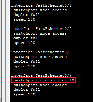
Therefore, we need to synchronize the vlan number for FastEthernet 0/1 - 4:
Switch(config)#int fastEthernet 0/4
Switch(config-if)#switchport mode access
Switch(config-if)#switchport access vlan 1  ; or you can type "no switchport access because vlan1 is set by default
Q3. Choose the right cable to connect Switch0 to Switch1 and Switch2
A crossover cable is used to connect devices of the same type, such as two routers, two PCs, or two switches:
Q4. Configure those two links as trunk lines without using trunk negotiation between switches
In a scenario similar to this, connections like those among Switch0-3 is typically configured in trunk mode. This is because it is positioned in the intermediate path where all traffic, even those that may have a differenct vlan number, flows.
The way to set an interface in trunk mode is as follows:
Switch(config)#int gigabitEthernet 0/1
Switch(config-if)#switchport mode trunk
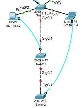
Switch(config-if)#no shutdown Let's check it out:
Switch#show interfaces trunk
Port        Mode         Encapsulation  Status        Native vlan
Gig0/1      on           802.1q         trunking      1
Gig0/2      on           802.1q         trunking      1
If you have completed the steps so far, the topology should appear as follows :