Bridge Loop
In the topology designed for redundancy as depicted below, imagine that broadcast traffic is incoming from Switch4, such as ARP:
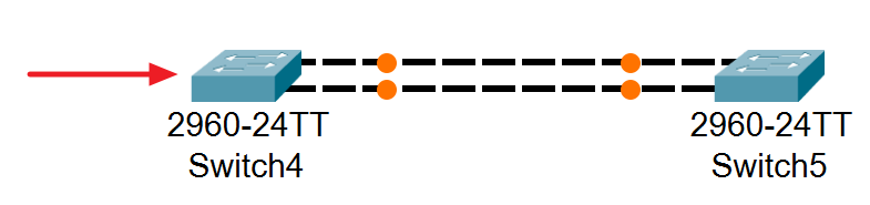
Switch4 would forward it to all ports except for the one from which the ARP traffic originated.
When Switch5 receives them, it also floods incoming ARP traffic from each of its ports to the other port respectively.
This progress would be repeated on both Switch4 and Switch5 alternatively with each other.
Spanning Tree Protocol
This happens because a port of a specific switch is connected to another port on the same switch itself.
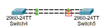
Spanning Tree Protocol (STP) prevents the occurrence of the previous situation by disconnecting a segment that form such a structure like the following examples:
#1
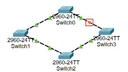
#2
Understanding the Process
Root Bridge
First, STP elects a root bridge, which serves as the reference point for determining which ports to block.
BPDU
Bridge Protocol Data Unit (BPDU) is used for electing a root bridge. All swtiches in a topology send this traffic to each other, and switches that receive BPDU traffic compare the bridge ID in the BPDU traffic with their own bridge ID.
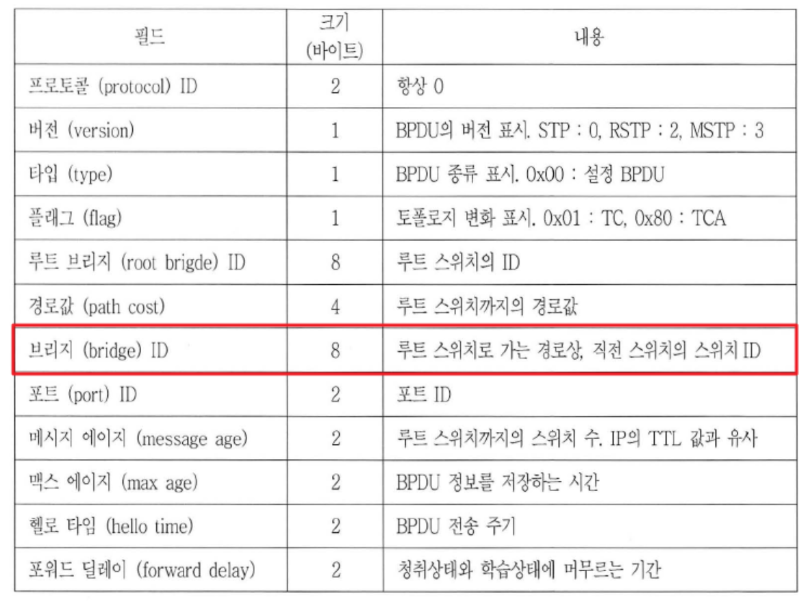
Among them, the switch with a lowest bridge ID would be elected as the root bridge.
In the previous example #2, Switch1 was elected as the root bridge:
Switch1#show spanning-tree
VLAN0001
  Spanning tree enabled protocol ieee
  Root ID    Priority    32769
             Address     000C.8578.36B9
             This bridge is the root
             Hello Time  2 sec  Max Age 20 sec  Forward Delay 15 sec

  Bridge ID  Priority    32769  (priority 32768 sys-id-ext 1)
             Address     000C.8578.36B9
             Hello Time  2 sec  Max Age 20 sec  Forward Delay 15 sec
             Aging Time  20

Interface        Role Sts Cost      Prio.Nbr Type
---------------- ---- --- --------- -------- --------------------------------
Fa0/1            Desg FWD 19        128.1    P2p
Fa0/2            Desg FWD 19        128.2    P2p
Port Mode
STP manages the topology by categorizing ports into three different mode types.
1. Root Port
An interface with the shortest path to the root bridge is configured as the Root Port.
The Root Port can handle both BPDU traffic and normal data.
2. Designated Port
Designated Port is simply referred to as a forwarding port. Also significant features about this is that a segment should have one designated port.
The Designated Port can handle both BPDU traffic and normal data.
3. Alternative Port(Block Port)
A port that is not elected as either Root Port or Designated Port will be configured as an Alternative Port. Since it cannot handle any traffic except for BPDU traffic, the segment with an Alternative Port is virtually a blocked link.
Port Status
The Port Status consists of the following five types:
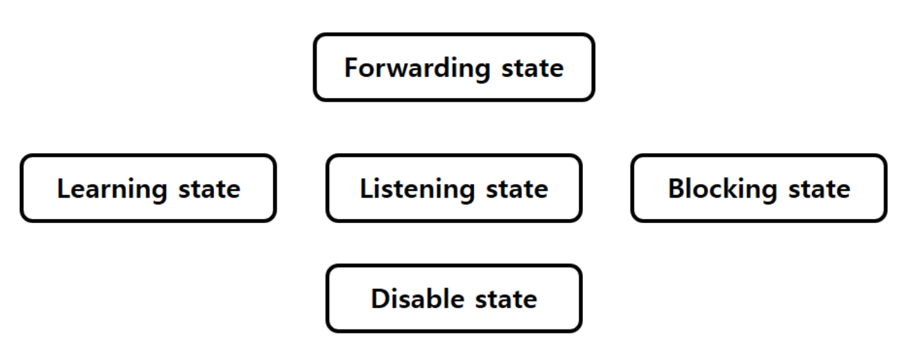
Let's take a brief look at each status one by one.
1. Listening State
The Listening State is set when a link is first connected.
| BPDU 송/수신 | MAC 주소 학습 | 데이터 전송 |
|---|---|---|
| O | X | X |
2. Learning State
When the Listening State remains for 15 seconds, the port is set into the Learning State.
It is the state that the port can learn MAC address through BPDU traffic.
| BPDU 송/수신 | MAC 주소 학습 | 데이터 전송 |
|---|---|---|
| O | O | X |
3. Forwarding State
When the Learning State remains for 15 seconds, the port is set into the Forwarding State.
It indicates that the port can send and receive all traffic, as well as learn MAC addresses.
| BPDU 송/수신 | MAC 주소 학습 | 데이터 전송 |
|---|---|---|
| O | O | O |
4. Blocking State
The enabled port which occurred any incident could be changed into the Blocking State immediately."
It can only handle BPDU traffic, not the others.
5.Disable State
It indicates that the port is not currently in use.