[논문 리뷰] Deformable Neural Radiance Fields using RGB and Event Cameras (ICCV 2023)
Paper Review
빠르게 움직이는 deformable한 object에 대해, 정교한 3D recon을 수행하기 위해서 Event Stream을 고려하는 Dynamic NeRF network 제안
1. Introduction
최근 NeRF의 발전으로 3D Scene을 implicit하게 represent하여 여러 View-point에서의 실제와 같은 이미지들을 효과적으로 합성할 수 있었다.
하지만 RGB image에 의존적인 기존의 방법으로, Deformable한 object가 존재하는 Dynamic한 scene을 3D reconstruction하기에는 limited frame rate, motion blur와 같은 한계가 존재했다.
Event camera data는 빠른 움직임에서의 Radiance change를 잘 포착하지만 event stream의 이점을 살리기 위해 아래와 같은 challenge가 존재한다.
- Event data만으로는 event가 발생한 pixel 위치의 absolute한 radiance를 알 수 없다.
- Event Stream에는 RGB 정보가 없음
- Event가 발생한 시점의 camera pose를 알 수 없다.
1번 challenge는 RGB와 Event를 함께 고려하는 hybrid System을 구현하여 해결하고,
2번 challenge는 time 축에서 spase한 RGB frame에 대한 camera pose을 활용하여 Event가 발생한 시점 t에서의 camera pose를 estimate하는 PoseNet을 훈련시켜 해결한다.
본 논문의 contribution은 아래와 같다.
- Event camera를 활용하여 처음으로 deformable neural radiance field를 모델링함
- Event camera의 연속적인 pose를 학습하는 method 제안
2. Related Work
Dynamic NeRF 간단 정리
기존의 NeRF가 → 로 mapping 해 주는 MLP를 학습시켰다면, time 축에서 변화하는 dynamic한 scene을 더 효과적으로 redering하기 위해 Dynamic NeRF(D-NeRF)는 time t를 추가로 고려한다. →
위 mapping은 하나의 network로 되는게 아니라, Deformation Network → Canonical Network 순으로 순차적으로 이루어 지는데
Deformation Network는 t 시점의 frame이 t=0이랑 비교했을 때 얼마나 차이가 나는지 예측하는 network로 → mapping한다.
t=0이랑 비교하는 이유:
Object의 Representational pose를 가지는 frame을 처음 시점에서의 frame으로 가정. 이 frame을 Canonical Space라고 한다.
물체가 움직여도 World 좌표에서의 위치 변화량을 잘 예측해서 움직이는 객체의 point를 계속해서 추적하기 위함이다.
Canonical Network는 시점 t의 을 위에서 구한 을 사용하여 t=0에 매핑시키고 거기서 를 estimate한다. →
3. Events in the Radiance Field
- 정의
- : 시점 t에서의 event camera & RGB camera의 6DoF pose를 표현하는 함수
- 6 DoF pose : (Rotation matrix ; Translation Vectors)
- : 2D location x (픽셀)에서 시점 t에 발생한 event e
- : Event camera가 측정하는 event e들의 집합
- : Sparse한 time 집합
- : Spare한 time에서 수집된 RGB image 와 Known Pose
- : 시점 t에서의 event camera & RGB camera의 6DoF pose를 표현하는 함수
⇒ 을 활용하여 → network를 모델링하는게 본 연구의 목적.
3.1 Mapping Events to 3D Rays
MLP PoseNet을 사용하여 시점 t에서의 event camera pose를 mapping해 주는 함수 을 구현한다.
PoseNet은 [-1, 1]로 normalize된 time t를 positional encoding ()을 통과시킨 후 MLP를 거쳐 screw axis representation ()로 mapping한다.
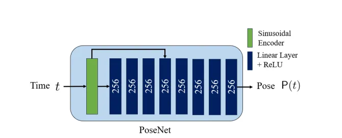
이를 통해 event가 발생한 시점에서의 Camera pose와 (x, y) location을 활용하여 event를 world 좌표계의 3D space로 projection할 수 있게 된다. 그 후에 Ray를 따라 3D space에서의 event point ()를 sampling할 수 있게 되고, 해당 point에서의 radiance와 density를 추정할 수 있다.
sparse한 RGB camera pose 와 시점 을 PoseNet 훈련에 사용.
pair data를 그대로 PoseNet 훈련에 사용하는게 아니라, 비어있는 시점에서 interpolation된 pose (residual pose)를 예측하도록 함.
3.2 Event Rays in the Deformable Radiance Field
시점 t의 3D point 을 canonical position 로 MLP을 사용하여 mapping 시키고, canonical representation 이 다른 MLP를 통과하여 color와 density를 estimate하게 된다.
Deformation Network로 그냥 MLP 사용했다는 걸 논문에서 장황하게 풀어씀
3.3 Rendering Event Ray for Supervision
- : event e에서 가장 가까운 RGB image
- event e (x, t)에서 시점 t와 sparse time set 을 비교해서 찾음
- : Effective한 event (유효한 이벤트들)
- 의 시점과 event e의 시점 t 사이에서 발생한 이벤트들의 개수를 뜻함
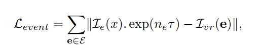
기본 NeRF의 방식을 그대로 사용해서 각 event에 대해 rendering된 color 와 event location (픽셀좌표 (x, y))에서의 RGB color 을 비교하여 loss term으로 삼고 RGB frame과 event 사이의 event 개수들을 고려한다.
위 loss term에서 는 event 발생 threshold라고 하는데…왜 쓰이는지 잘 모르겠음
3.4 Sampling Events
Event 집합 를 잘 만드는 방법 서술, 아래 두 가지 sampling 방법을 모두 사용함
Void Sampling 기법
Rendering 된 Scene의 visual consistency를 위해 time t에서 event가 발생하지 않은 pixel location x를 임의로 선택하고, 해당 위치의 빈 event (Void event)를 에 반영해 주었다.
color 변화가 심하게 발생하지 않는 부분에서도 event를 통한 rendering을 수행할 수 있도록 하기 위함
Active Sampling 기법
Scene에서 움직이는 부분의 event를 우선적으로 active하게 sampling할 수 있도록 했다.
RGB frame 이 있는 시점 에서 warp field 을 rendering 해서 해당 시점의 움직임의 magnitude를 측정하고 움직임이 많은 픽셀 주변의 event가 많이 sampling될 수 있도록 했다는데 더이상의 설명이 없고 인용도 없음…
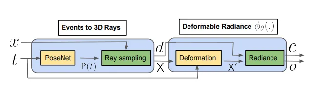
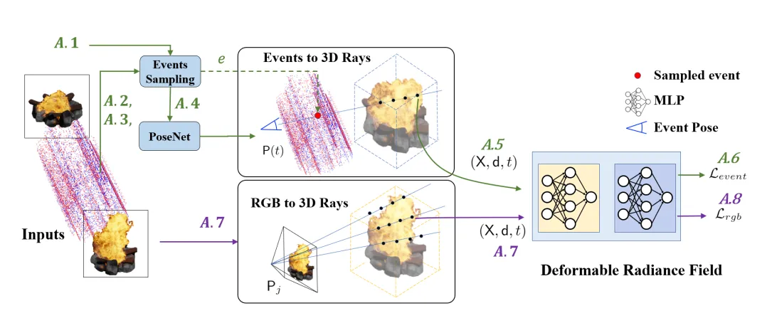
4. Method Overview
-
Warp field rendering (Active sampling) + void sampling해서 event 집합 생성
-
각 event에 대해 PoseNet을 통과시켜 pose를 획득
-
event pose와 pixel 위치를 통해 event ray 을 rendering
-
을 사용하여 event loss를 구함
-
Image에 대해서도 똑같이 ray sampling () 후 ray 을 rendering
-
계산
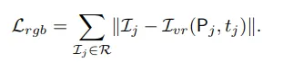
- GT rgb pixel 값과 pose와 time이 입력되어 rendering한 rgb 사이의 loss
-
()
5. Implementation Details
- Deformation network에 witdh:128인 6-layer MLP 사용
- Nerfies 를 baseline 모델로 사용한 것 같음.
- RTX 2080 Ti 4개를 훈련에 사용
- Synthetic data 로 blender에서 3D환경 구축하고, ESIM으로 event를 simulate함.
- Github에서 Vid2E 사용했다고 되어있음.
- Real data:
- HS-ERGB: Video interpolation Dataset
- CED: Color Event Camera Dataset
- EVIMOv2
Limitation
- 밝기만 변하고 색이 변하지 않는 event에서 color rendering을 잘 못하는 경우 발생.
평가
- Event data의 장점을 잘 살려서 딱 필요한 분야 (움직이는 object의 3D recon)에 잘 사용한 것 같음.
- 구조는 단순해 보임