Shaders and the Rendering Pipeline
렌더링 파이프라인(Rendering Pipeline)?
렌더링 파이프라인(Rendering Pipeline) 또는 그래픽스 렌더링 파이프라인(Graphics rendering pipeline)이라 부르는 과정은 3차원으로 만들어진 모델을 2차원에 투영하는 렌더링 과정의 프로세스를 자세하게 표현한 것이다. 컴퓨터에 데이터로 존재하는 3D 리소스가 모니터에 출력되는 과정이 렌더링 파이프라인을 따르게 된다. 아래와 같은 과정에 따라 화면에 도형을 표시할 수 이쓰며, 황색 박스로 된 과정이 조작 가능한 (Programmable) 단계이다.
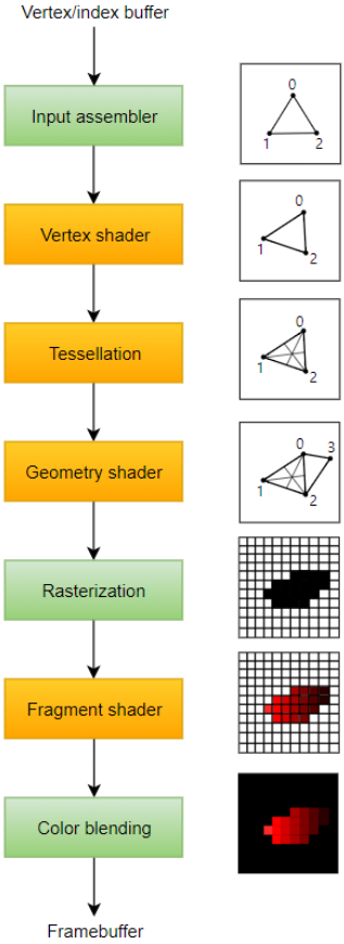
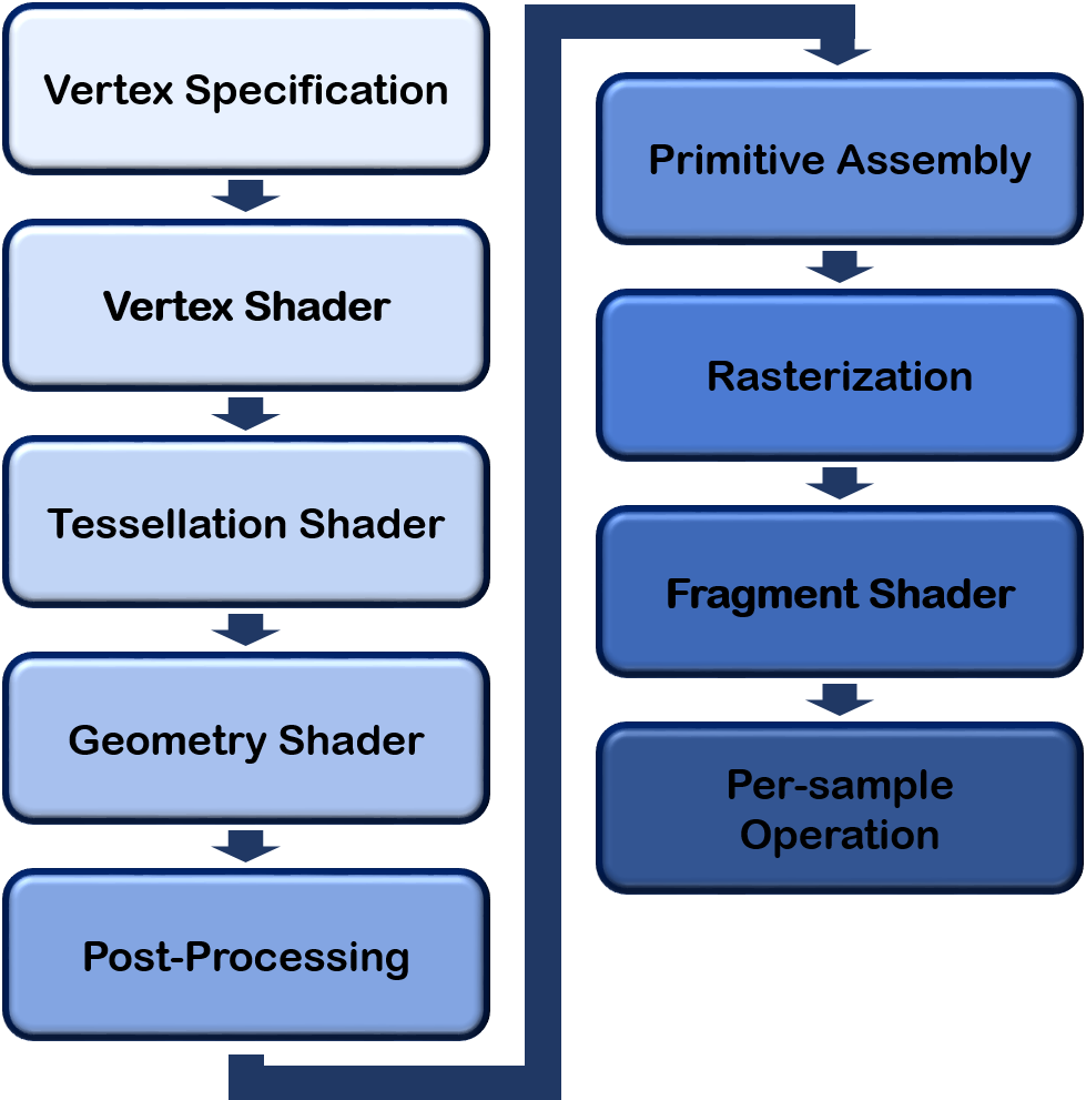
좀 더 세부적으로 나타내면 9단계로 나타낼 수 있다.
Vertex Specification
- Vertex는 공간에서의 한 점(point), 일반적으로 (x, y, z)로 정의된다.
- 기본 요소는 하나 이상의 정점을 사용하여 정의된 단순한 모양이다.
- 일반적으로 삼각형을 사용하지만, 별도의 점(point), 선(line), 면(Quad)을 쓰기도 한다.
정리하자면 우리가 그릴 삼각형의 꼭짓점 정보를 작성하고 저장하는 과정을 의미한다. 이 정보는 셰이더로 전달되어서 처리된다. 셰이더는 쉽게 말하면 GPU에서 실행되는 프로그램이다. 따라서 꼭지점 정보를 GPU로 보내야한다.
하지만 매 프레임마다 우리가 원하는 꼭짓점들을 그려야하고 매번 CPU에 있는 꼭짓점 정보를 GPU로 보내는 것은 효율적이지 않다. 그래서 우리는 꼬지점 정보를 그래픽 카드 메모리 공간에 저장하고, GPU가 이를 필요할 때마다 부르도록 설정한다.이를 위해 VAOs, VBOs를 사용한다.
VAOs :
Vertex Array Objects; defined WHAT data a vertex has (position, colour, texture, normals, etc)
VBOs :
Vertex Buffer Objects ( Attribute Pointers define where and how shaders can access vertex data ).
점(Pointer)에 대한 정보를 OpenGL Object에 저장한다.
OpenGL Object : 기본적으로 OpenGL은 상태 기계이다. 따라서 일련에 설정된 state에 따라서 작동한다. 그리고 이 state를 바꾸지 않으면 OpenGL 함수들도 그 경향을 유지한다. 이렇게 OpenGL은 state가 바뀌지 않는 한 가장 최근에 설정된 값으로 돌아가는 기계라고 할 수 있고, OpenGl Object는 이러한 state를 담고 있는 구조체 같은 것이다.
따라서 OpenGL Object를 OpenGL Context에 연결하면 OpenGL 함수들은 context에 연결된 state를 current state라고 인식하고, 이를 바탕으로 작동한다.
예컨대, 우리가 A라는 삼각형의 꼭짓점 정보를 담은 VBO를 GL_ARRAY_BUFFER이라는 OpenGL context에 연결(bind)하면 이 연결을 깨기 전까진 OpenGL 함수들이 A 삼각형의 꼭짓점 정보를 바탕으로 작동한다. 참고로, GL_ARRAY_BUFFER과 같은 특정한 OpenGL context 지점을 target이라고도 한다.
이러한 target들은 실제로는 unsigned int 값이지만, 비유적으로 본다면 주소와도 같은 것이다. 이 주소에 VBO라는 값을 저장한다고 보면 된다.
VAOs 와 VBOs를 생성함으로써 그래픽 카드에 데이터를 저장하고 더 빠르게 접근할 수 있다.
Creating VAO/VBO
- Generate a VAO ID
- Bind the VAO with that ID
- Generate a VBO ID
- Bind the VBO with that ID
(noew you're working on the chosen VBO attatched to the chosen VAO) - Attatch the vertex data to that VBO
- Define the Attribute Pointer formatting
- Enable the Attributer Pointer
- Unbind the VAO and VBO, ready for the enxt object to be bound
Initiating Draw
- Activate Shader Program you want to use
- Bind VAO of object you want to draw
- Call glDrawArrays, which initiates the rest of the pipeline
VAO, VBO를 직접 생성하는 과정이 담긴 문서가 있는데 궁금하면 참고하자.
Vertex Shader (Programmable)
정점들의 정보로 도형은 생성되었지만 공간 좌표계를 변환할 필요가 있다.
기본적으로 도형들은 자신만의 좌표계인 Local Space의 좌표를 가지는데, 모든 물체들이 하나의 월드에 위치하도록 Local Space에서 World Space로 변환하고, 실제 플레이어가 바라보는 카메라가 중심이 되는 공간인 View Space(Camera Space)로 변환해준다.
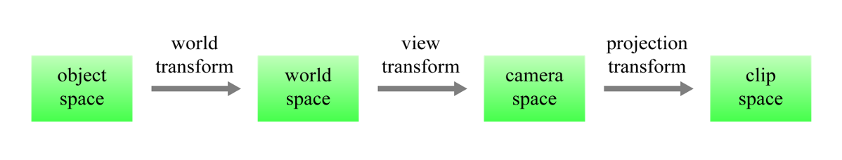
좌표게 변환에 대한 블로그를 참고하면 이해할 때 도움이 된다.
- Handles vertices individually
- NOT optional
- Must store something in gl_Position as it is used by later stages
- Can specify additional outputs that can be picked up and used by user-defined shaders later in pipeline
- Inputs consist of the vertex data itself
간단하게 말하자면 Shader는 vertex 정보들을 화면에 보여질수 있도록 변환하는 작업을 하는 프로그램(명령어 집합)이고, 스크린 위에 낱개의 픽셀마다 실행되며 이 실행들이 한번에 일어난다.
간단한 정점 셰이더 예제를 보자.
Shaders are pieces of code written in GLSL(OpenGL Shading Language), or HLSL (High-Level Shading Lenaguage) if you're using Direct3D.
이때 GLSL은 C를 기반으로 하고 있다.
GLSL
#version 330 // GLSL 버전 지정

layout (location = 0) in vec3 posl; // pos 라는 이름의 3차원 벡터 입력 변수를 정의, 레이아웃 위치 0에 바인딩

void main() {
	gl_Position = vec4(pos, 1.0); // OpenGL 내장 변수 gl_position에 값을 할당
}
Cpp
void main(void) {
    const vec4 vertices[3] =
        vec4[3](vec4( 0.25, -0.25, 0.5, 1.0),
                vec4(-0.25, -0.25, 0.5, 1.0),
                vec4( 0.25, 0.25, 0.5, 1.0));

    // 화면에 3개의 점을 그린다.
    gl_Position = vertices[gl_VertexID];
}
gl_Position : 스크린상의 점의 위치를 가리키는 값을 저장하고 있다. 4개의 매개변수가 필요해서 vec4로 값을 넘긴다.
Tessellation (Programmable)
Tesselation 단계는 주어진 모델의 정점을 더 잘게 쪼개어 디테일하게 표현할 때 사용한다.
일반적으로 가까운 거리의 물체는 고해상도로, 먼 거리의 물체는 저해상도로 표현하여 성능을 향상시키는데, 고해상도로 표현되었을 때 보여져야 할 텍스쳐 형태를 높이 맵으로 저장해놓고 실제 모델에 필요한 만큼의 레벨만큼만 적용하는 식으로 테셀레이션을 활용하면 하나의 모델에 대해 여러 해상도의 모델 데이터를 가지고 있을 필요가 없다.
이는 LOD(Level of Detail)을 적용하여 여러 해상도로 표현 가능한 모델을 마련했는데, 그 모델들끼리의 변환이 부자연스러운 경우를 Tesselation으로 자연스럽게 표현할 수 있는 것이다.
- Allows you to divied up data in to smaller primitives
- Relatively new shader type, appeared in OpenGL 4.0
- Can be used to add higher levels of detail dynamically
Geometry Shader (Programmable)
기본 도형에서 정점을 추가하거나 삭제하여 모델을 변경할 수 있는 셰이더이다. Geometry Shader로 정점 정보를 조금 추가하여 표현할 수 있는 모델이라면 그만큼의 정점 정보를 빼고 저장할 수 있으니 디스크 용량과 그래픽 메모리 절약에 도움이 될 수도 있으며, 테셀레이션 등으로 추가된 정점들을 표현할 때도 사용된다.
즉, Vertex Shader에서 생성되지 않은 임의의 점, 선, 삼각형 생성 및 수정할 수 있는 셰이더로 실제 객체로 생성한 캐릭터의 모양을 바꿔보이게 하거나, 실제 객체로는 존재하지 않지만 눈에 보이는 도형을 그릴 수 있다.
- Vertex Shader handles vertices, Geometry Shader handles primitives(group of vertices)
- Takes primitives then "emits" their vertices to create the given primitive, or even new primitives
- Can alter data given to it to modify given primitives, or even create new ones
- Can even alter the primitive type (poins, lines, triangles, etc)
Vertex Post-Processing
- Transform Feedback (if enabled) :
- Result of Vertex and Gemoetry stages saved to buffers for later use. - Clipping :
- Primitives that won't be visible are removed (don't want to draw things we can't see )
- Positions converted from "clip-space" to "window space"
Primitive Assembly
Vertex Processing을 통해 2차원의 점이 생겼다. 그런데 점으로 존재하기 위해 계산한 것이 아니다. 점 사이에 선을 긋거나, 점들을 모아서 Primitive를 만들어서 색칠하거나 하는 등의 목적으로 점을 계산한 것이다.
그래서 이 점들이 다각형인지, 삼각형인지, 선인지 알게 하는 과정이다. 즉, 점 사이에 선을 긋거나, 여러 점을 모아서 다각형을 만드는 과정이다.
Cliping?
카메라 입장에서는 시야 밖의 부분이 보이질 않는다. 이 보이지 않는 바깥 부분을 버리는 과정이다.
경우에 따라서 너무 가까이 있거나, 멀리 있어서 버리는 경우도 있다.
- Vertices are converted in to a series of primitives
- So if rendering triangles : 6 vertices would become 2 triangles (3 vertices each).
- Face culling
- Face culling is the removal of primitives that can't be seen, or are facing "away" from the viewer. We don't want to draw something if we can't see it
Rasterization
정점 정보를 완전히 결정한 3D 도형을 실제 픽셀 데이터로 변환해주는 단계이다. 이때 우리가 가진 정점 데이터는 말그대로 정점의 데이터이고, 정점 사이의 공간은 보간(Interpolation)을 통해 메워주어야 한다.
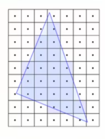
즉, 화면에서 각각의 픽셀이 다각형에서 어떤 부분에 해당하는지 알아내는 과정이다. 삼각형이 2차원에 그려져야 하므로, 각각의 픽셀이 어떤 삼각형에 해당하는지 알아야 한다. 그래야 각 픽셀을 색칠할 수 있다. 이 때 알아낸 각각 하나의 점을 "Fragment"라고 한다.
중요한 점은 정점 정보를 통해 결정한 도형을 실제 픽셀 데이터로 바꾼다는 것이다. 결국 픽셀 단위로 이미지를 형성해서 내보내야 되기 때문에 이러한 과정이 필요하다.
- Converts primitives in to "Fragments"
- Fragments are pieces of dat a for each pixel, obtained from the rasterization process
- Fragment data will be interporlated based on its position relative to each vertex
Fragment Shader (Programmable)
Pixel Shader라고도 부르며, 래스터화된 도형에 텍스쳐 매핑, 범프 매핑, 노말 매핑 등의 기법으로 텍스쳐를 입혀 색을 표현한다. 또한, 정점의 법선 벡터 정보를 통해 조명(Lighting) 처리도 해당 셰이더에서 이루어진다.
즉, Rasterization 과정으로 정해진 Fragment 각각에 어떤 색을 칠할 지를 결정하는 단계라고 생각하면 된다.
- Handles data for each fragment
- Is optional but it's rare to not use it. Exceptions are cases where only depth or stencil data is requried (more on depth data later)
- Most important output is the colour of the pixel that the fragment covers.
- Simplest OpenGl programs usually have a Vertex Shader and a Fragment Shader
Simple Example
#version 330

out vec4 colour;

void main() {
	colour = vec4(1.0, 0.0, 0.0, 1,0);
}
Per-Sample Operations
- Series of tests run to see if the fragment should be drawn
- Most important test : Depth test. Determines if something is in front of the point being drawn
- Colour Blending : Using defined operations, fragment colours are "blended" together with overlapping fragments. Usually used to handle transparent objects
- Fragment data written to currently bound Framebuffer (usually the default buffer ,more on this later)
- Latly, in the application code the user usually defines a buffer swap gere, putting the newly updated Framebuffer to the fron.
Shader
- Shaders Programs are a group of shader (vertex, Tessellation, Gemotry, Fragment...) associated with one another
- They are created in OpenGl via a series of functions
Create Shader Program
- Create empty program
- Create empty shaders
- Attatch shader source cod to shaders
- Compile shaders
- Attach shaders to program
- Link program (creats executables from shaders and links them together)
- Validate proram (optional but highly advised because debugging shaders is a pain)
Using a Shader Program
- When you create a shaer, an ID is given (like with VAOs and VBOs)
- Simply call glUseProgram(shaderID)
- All draw calls from then on will use that shader, glUseProgram is used on a new shaderID, or on '0' (meaning 'no shader')
요약
Rendering Pipeline consists of several stages.
• Four stages are programmable via shaders (Vertex, Tessellation, Geometry, Fragment).
• Vertex Shader is mandatory.
Vertices: User-defined points in space.
• Primitives: Groups of vertices that make a simple shape (usually a triangle). Fragments: Per-pixel data created from primitives.
Vertex Array Object (VAO): WHAT data a vertex has.
• Vertex Buffer Object (VBO): The vertex data itself.
• Shader programs are created with at least a Vertex Shader and then activated before use.
이후에 작성될 다음 문서 OpenGL (4)에 작성된 코드와 함께 보면 이해가 더 쉬울 것이다.